Description
Technical Overview
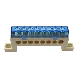
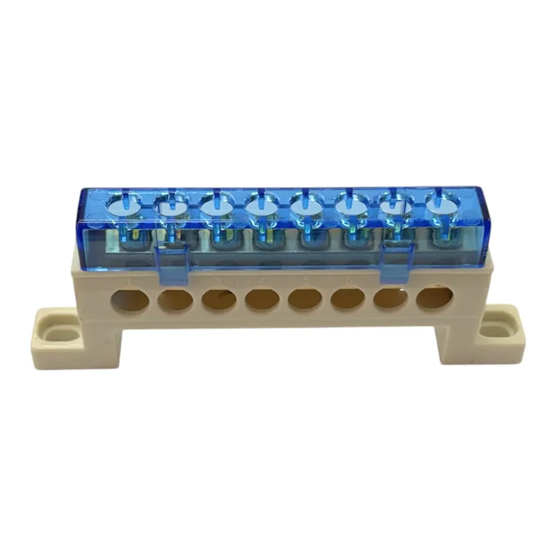
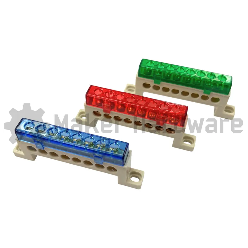
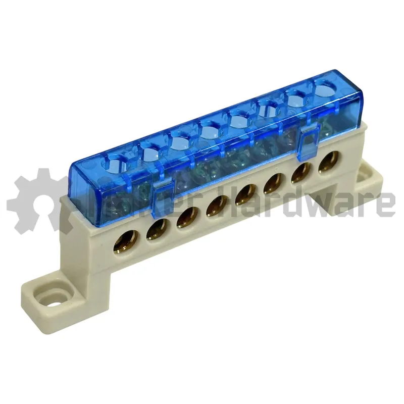
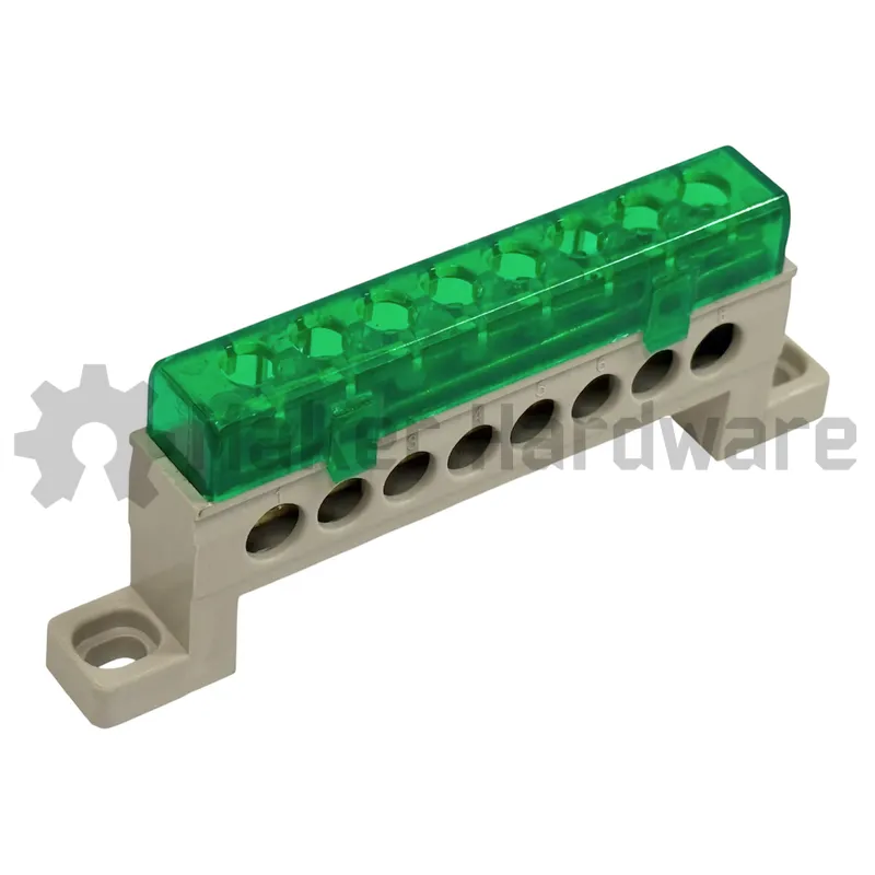
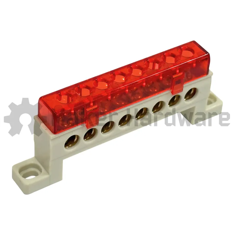
The dustproof base terminal – 8 pin acts as a modular mounting platform. This rigid structure consolidates multiple electrical connection points. Specifically, a zero-wire distribution box architecture utilizes continuous, bridge-type electrolytic-grade copper busbars. As a result, these busbars connect all ports electrically. This monolithic substrate design successfully eliminates individual jumpers or solder joints. Consequently, the layout mitigates resistance hotspots and prevents thermal expansion misalignment over time.
Furthermore, a durable insulation housing pairs with a polycarbonate protective lid to shield the base terminal. This combination provides robust structural protection while maintaining standardized hole spacing and pitch configurations. For installation, users mount the system directly onto a chassis rail via pre-drilled side slots. Finally, the terminal accepts stranded conductors and crimped spade lugs. This connection method absorbs structural vibration and safeguards fragile termination interfaces.
Applications
This base terminal – 8 pin delivers high-reliability electrical distribution. It performs exceptionally well in demanding environments prone to mechanical stress, thermal movement, and particulate exposure. For instance, operators install it inside CNC machine control panels, industrial automation systems, and factory-floor machinery controls.
In addition, the dustproof, IP65-rated polycarbonate enclosure offers high effectiveness. It thrives where metal shavings, coolant mist, or grinding debris accumulate. Therefore, the unit serves as a dependable replacement for aging DIN-rail mounted terminals. It also replaces traditional screw or spring-clamp blocks. Ultimately, it excels in conveyor systems, automotive manufacturing lines, and mixed-signal environments where PLCs interface analog sensors alongside digital actuators.
Technical Specifications
Maker Store Tips and Tricks
-
Size Selection: Match the required number of physical connections against the maximum capacity per row (e.g., utilize a 7-port variant only when connecting more than six devices).
-
Phase Separation: Physically segregate input and output circuits across the internally bridged block to eliminate cross-talk risks in mixed-signal PLC setups.
-
Grounding Capability: Utilize the designated grounding pin beneath the casing to bond the terminal to earth ground via a dedicated lug.
-
Pre-Installation Labeling: Apply heat-shrink tags (e.g., “MOTOR_1_IN”) to every entry point prior to final installation to ensure long-term troubleshooting clarity against oil and residue buildup.
-
Torque and Insertion: Insert stranded conductors directly or via crimped spade lugs into the ports, and tighten the locking nut until snug; do not overtighten as torque tolerances are matching embedded gauge specifications.
-
Post-Installation Testing: Verify continuity by testing the voltage drop across adjacent ports while the system is powered down. Inspect the internal compression integrity if readings exceed 0.05 ohms