Many people have asked me if Maker Store has a camera slider kit. In response to demand I have put together a build using parts available from Maker Store that is suitable for a light weight camera such as a GoPro. The slider uses a carriage running on a V-Slot rail, a small stepper motor, an Arduino Uno and an infrared remote. The included Arduino sketch allows for the use of the IR remote to control the speed of the carriage.
Below is a list of parts and instructions on how to build the DIY Arduino Controlled Camera Slider.
Bill of Materials:
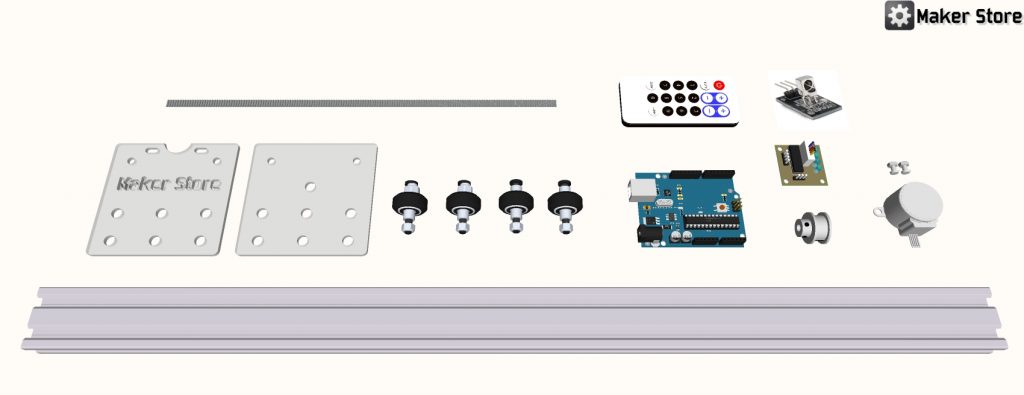
Camera Slider Plates:
The camera slider plates can be either purchased from Maker Store or you can cut your own using either a CNC router or Laser cutter. The Maker Store plates are cut from 3mm thick perspex but 3mm aluminum will word just as well.
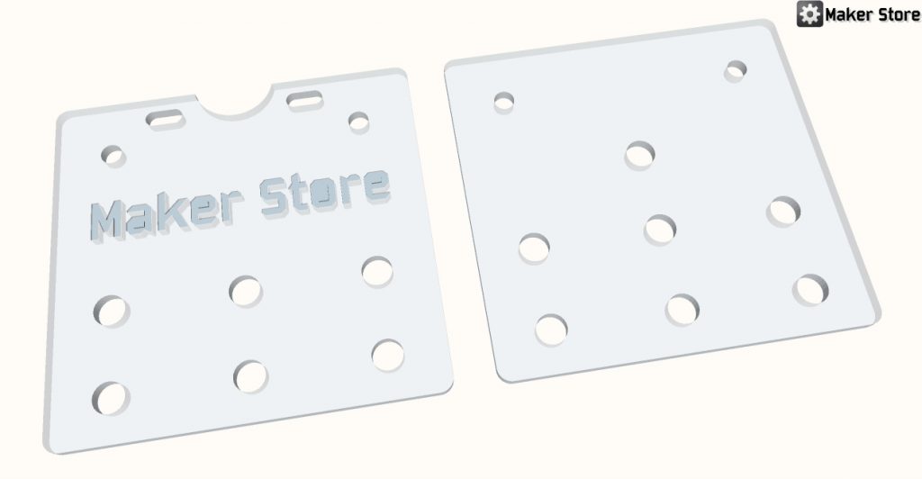
Here is the Sketchup file for the plates:
[wpfilebase tag=file id=95 /]After the plates are cut/purchased check the holes for the correct sizes by running either a 5mm or 7mm drill bit through. This will make sure that when you put all the screws and eccentric spacers in they fit without effort.
Assembly:
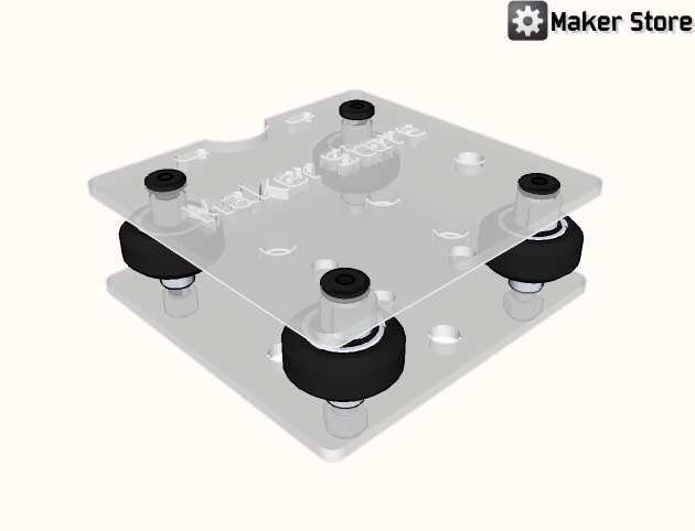
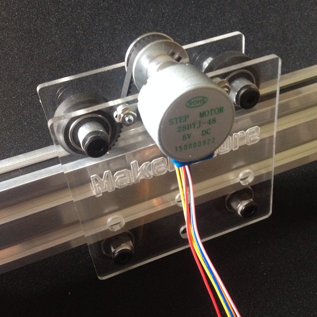
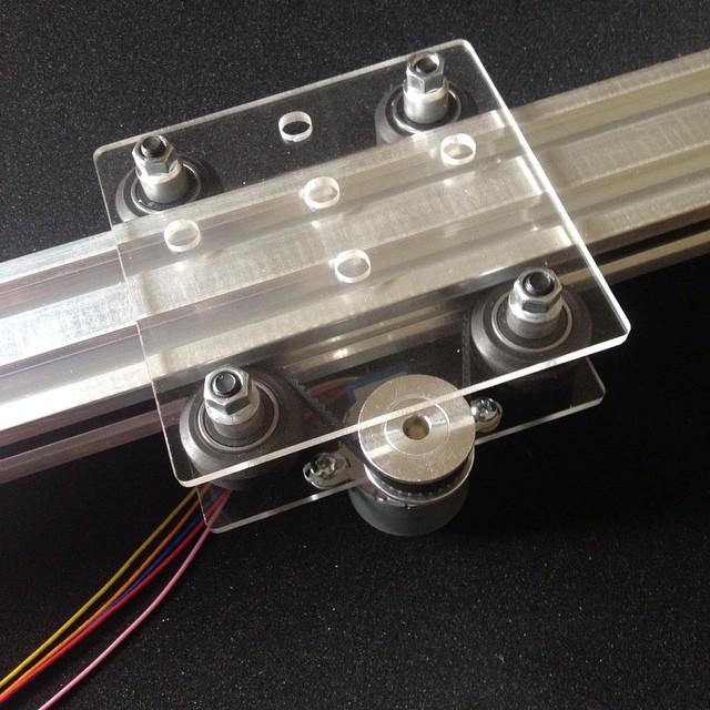
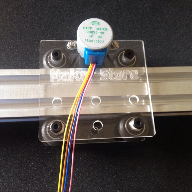
1. Using the 35mm screws (not the 25mm that come with the solid V-Wheels) assemble the carriage as per the drawings below. Make sure to use the eccentric spacers on one side of the carriage. Do not tighten the lock nut on the screw with the eccentric spacers yet. It is kept loose to allow for adjustment.
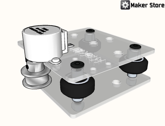
Click on the images to open a larger one in a new window.
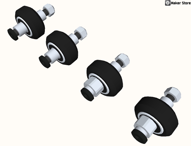
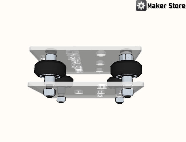
2. Put the timing pulley on the stepper motor. Add the stepper motor to the bottom plate.
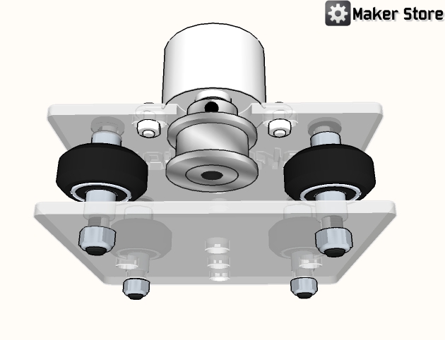
3. Before putting the carriage onto the rail, make sure to attach your camera mounting screw or other mechanism. Slide the completed carriage onto the V-slot rail, adjust the eccentric spacers so that there is no wobble on the rail, and tighten the lock nuts. Do not over tighten the eccentric spacers or the wheels will jam or the stepper will not be strong enough to pull the carriage.
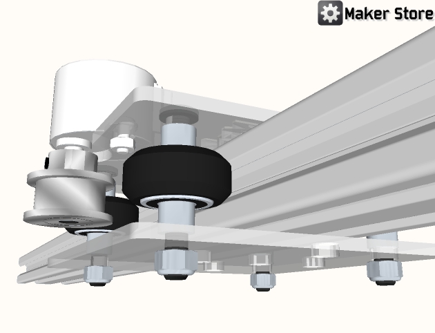
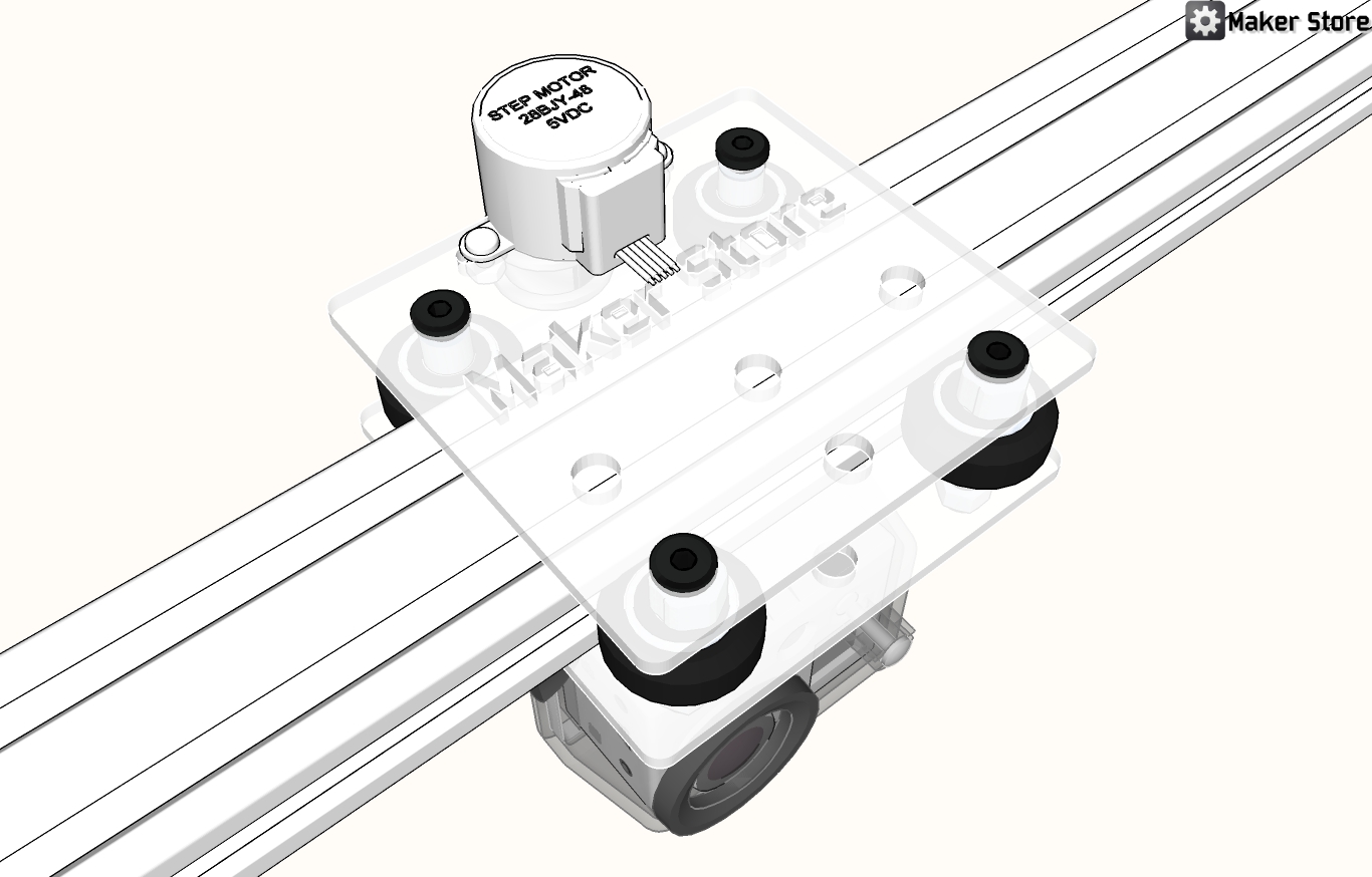
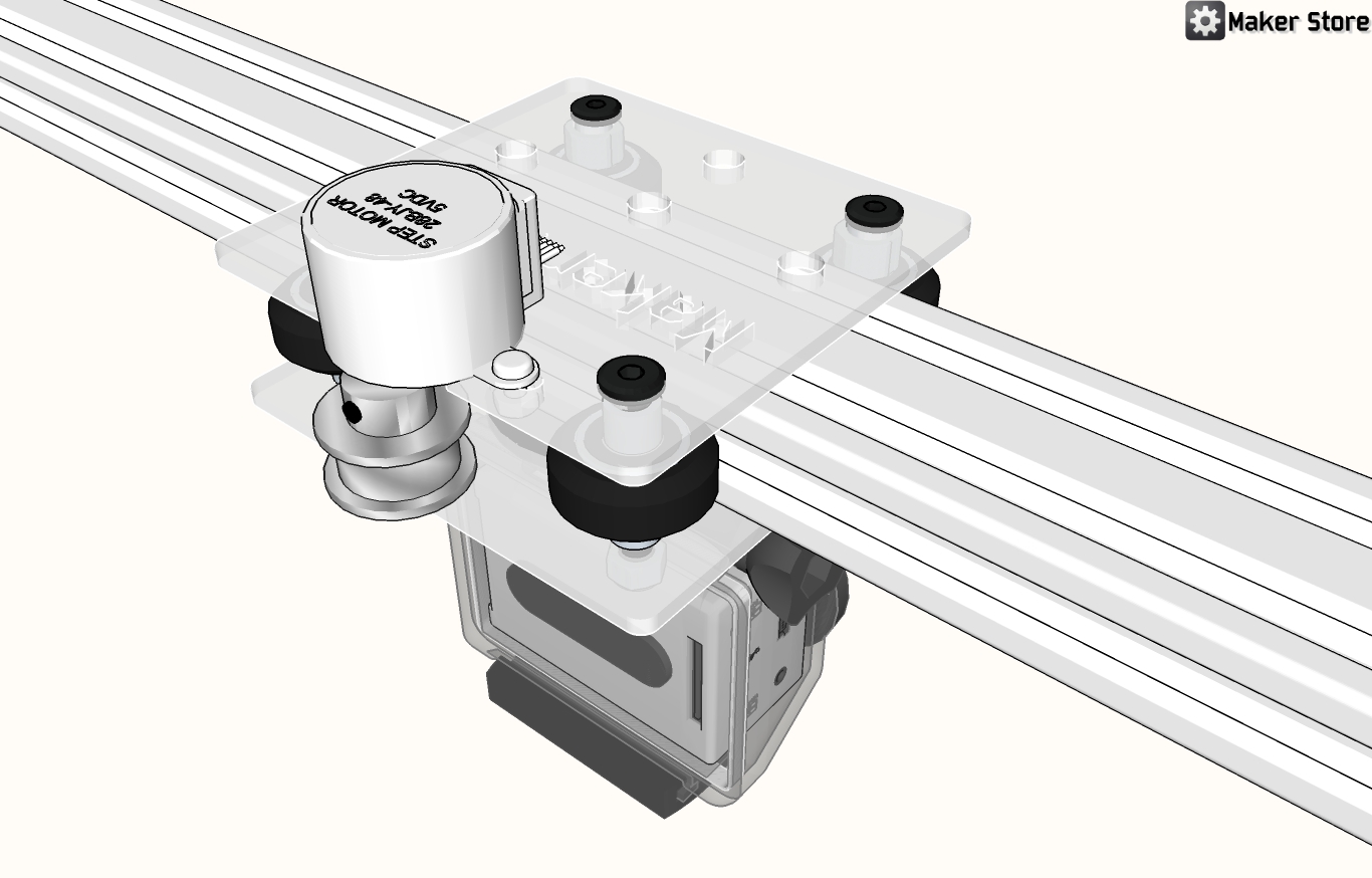
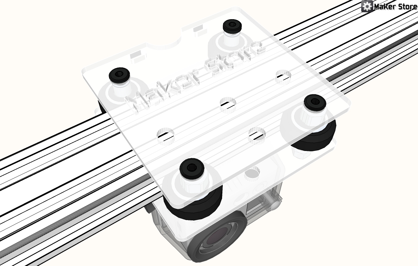
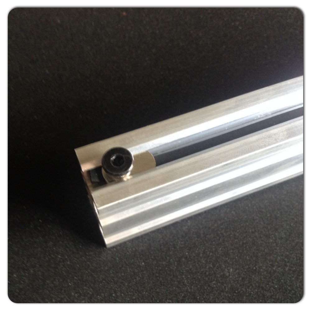
4. Slide the timing belt under the wheels and loop over the timing pulley. Pull the belt taught, but not too tight and secure at each end with a t-nut and screw.
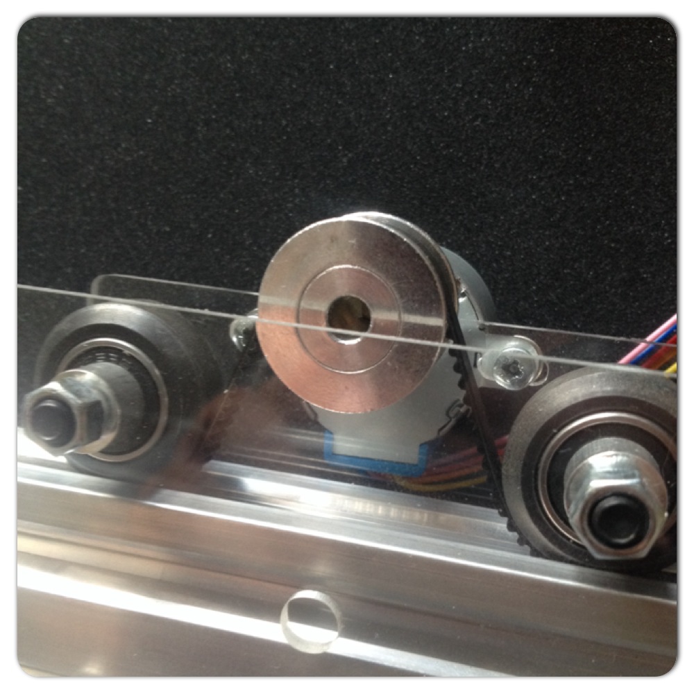
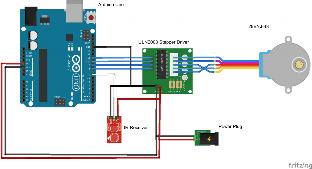
5. Attach the stepper motor, driver board, IR receiver, power supply and Arduino Uno as per the diagram below. Use a small breadboard to make the connections easier.
6. Upload the Camera Slider sketch to the Uno:
[wpfilebase tag=file id=96 ]/* Maker Store Camera Slider Stepper IR Receiver Button Decoder Example Software Sketch
based on code by terry@yourduino.com
Get Library at: https://github.com/shirriff/Arduino-IRremote
Unzip folder into Libraries. RENAME folder IRremote
steven@makerstore.com.au */
/*-----( Import needed libraries )-----*/
#include "IRremote.h"
#include <Stepper.h>
/*-----( Declare Constants )-----*/
int receiver = 7; // pin 1 of IR receiver to Arduino digital pin 7
/*-----( Declare objects )-----*/
IRrecv irrecv(receiver); // create instance of 'irrecv'
decode_results results; // create instance of 'decode_results'
//The pin connections need to be 4 pins connected
// to Motor Driver In1, In2, In3, In4 and then the pins entered
// here in the sequence 1-3-2-4 for proper sequencing
Stepper small_stepper(32, 8, 10, 9, 11); //
/*-----( Declare Variables )-----*/
int Steps2Take;
int StepSpeed;
void setup() /*----( SETUP: RUNS ONCE )----*/
{
Serial.begin(9600);
Serial.println("Maker Store Camera Slider Stepper IR Receiver Button Decoder");
Serial.println("Questions: steven@makerstore.com.au");
irrecv.enableIRIn(); // Start the receiver
StepSpeed = 500; //set default speed
}/*--(end setup )---*/
void loop() /*----( LOOP: RUNS CONSTANTLY )----*/
{
small_stepper.setSpeed(StepSpeed); // speed from the IR signal
if (irrecv.decode(&results)) // have we received an IR signal?
{
// Serial.println(results.value, HEX); UN Comment to see raw values
translateIR();
irrecv.resume(); // receive the next value
}
{
small_stepper.step(Steps2Take); // direction from the IR signal
}
}/* --(end main loop )-- */
/*-----( Declare User-written Functions )-----*/
void translateIR() // takes action based on IR code received
// describing KEYES Remote IR codes
{
switch(results.value)
{
case 0xFF629D: Serial.print(" Speed +20 / Speed="); StepSpeed = StepSpeed +20;Serial.println(StepSpeed); break;
case 0xFF22DD: Serial.println(" LEFT"); Steps2Take = -1;break;
case 0xFF02FD: Serial.println(" -STOP-"); Steps2Take = 0; break;
case 0xFFC23D: Serial.println(" RIGHT"); Steps2Take = 1; break;
case 0xFFA857: Serial.print(" Speed -20 / Speed="); StepSpeed = StepSpeed -20;Serial.println(StepSpeed); break;
case 0xFF6897: Serial.println(" Speed 10"); StepSpeed = 10; break;
case 0xFF9867: Serial.println(" Speed 50"); StepSpeed = 50; break;
case 0xFFB04F: Serial.println(" Speed 75"); StepSpeed = 75; break;
case 0xFF30CF: Serial.println(" Speed 100"); StepSpeed = 100; break;
case 0xFF18E7: Serial.println(" Speed 200"); StepSpeed = 200; break;
case 0xFF7A85: Serial.println(" Speed 300"); StepSpeed = 300; break;
case 0xFF10EF: Serial.println(" Speed 400"); StepSpeed = 400; break;
case 0xFF38C7: Serial.println(" Speed 500"); StepSpeed = 500; break;
case 0xFF5AA5: Serial.println(" Speed 900"); StepSpeed = 900; break;
case 0xFF42BD: Serial.print(" Direction="); Serial.print(Steps2Take);Serial.print(" / Speed="); Serial.println(StepSpeed); break;
case 0xFF4AB5: Serial.println(" 0"); break;
case 0xFF52AD: Serial.println(" #"); break;
case 0xFFFFFFFF: Serial.println(" REPEAT");break;
default:
Serial.println(" TRY AGAIN ");
}// End Case
} //END translateIR
/* ( THE END ) */
7. Test your setup. Using the remote check that you get the following:
| BUTTON | ACTION |
| LEFT ARROW | Carriage travels left |
| RIGHT ARROW | Carriage travels right |
| UP ARROW | Speed increases by 20 |
| DOWN ARROW | Speed decreases by 20 |
| OK | Stop |
| 1 | Speed set to 10 |
| 2 | Speed set to 50 |
| 3 | Speed set to 75 |
| 4 | Speed set to 100 |
| 5 | Speed set to 200 |
| 6 | Speed set to 300 |
| 7 | Speed set to 400 |
| 8 | Speed set to 500 |
| 9 | Speed set to 900 |
| * | Prints current speed and direction to serial |
If you get anything different then edit the sketch to suit your setup.
Please note that I am not a Arduino expert. If anyone has a better sketch then please let me know and I will add it here!
8. Tweak, and have fun with your DIY Arduino controlled camera slider.
9. Send photos of your builds to builds@makerstore.com.au and we will list them here!

[ess_grid settings='{“entry-skin”:”1″,”layout-sizing”:”boxed”,”grid-layout”:”even”,”spacings”:”0″,”rows-unlimited”:”off”,”columns”:”5″,”rows”:”3″,”grid-animation”:”fade”,”use-spinner”:”0″}’ layers='{“custom-youtube”:{“00″:”RACr4xPukyk”},”custom-type”:{“00″:”youtube”},”custom-ratio”:{“00″:”0″},”use-skin”:{“00″:”-1″}}’][/ess_grid]