Description
Technical Overview
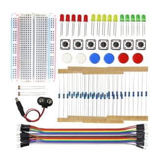
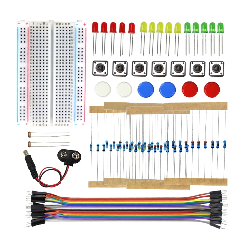
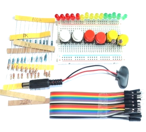
The Arduino Starter Pack #1 contains a foundational collection of loose prototyping hardware. In addition, it provides discrete electronic components for circuit experimentation. Specifically, this bundle serves as an entry-level kit. Therefore, you can easily assemble simple electronic circuits before you integrate a programmable microcontroller. Furthermore, the kit features a solderless breadboard. This board establishes secure electrical connections between your components. As a result, it completely eliminates the need for thermal soldering tools.
Additionally, the kit supplies basic control elements, passive devices, and light-emitting components. Consequently, these parts facilitate basic electrical engineering exercises. In particular, the package offers assorted light-emitting diodes (LEDs) in various colours. It also contains standard push buttons, mechanical switches, fixed resistors, and a light-dependent resistor (LDR). Technical users employ the LDR for optical sensing. Next, a 9V battery plug supplies primary electrical current to the breadboard rails. You can route this power easily using the included flexible jumper wires. However, please note one limitation. This bundle functions strictly as a hardware component set. Therefore, it does not include an Arduino microcontroller board, a USB interface cable, or embedded software.
Applications
Students and electronics hobbyists widely use this component bundle. Specifically, they implement it in introductory laboratory experiments and basic prototyping routines. For instance, you can employ the discrete components to build fundamental analog circuits. To do this, you combine the fixed resistors and the light-dependent resistor into voltage divider networks. Furthermore, you can connect the push buttons and assorted LEDs together. As a result, you create manual switching matrices, visual indicator arrays, and basic logic gate simulations.
First, you establish a basic understanding of these component behaviors. Afterwards, you can expand the circuit into a fully automated system. To achieve this automation, you must introduce an external microcontroller board. Specifically, you supply an independent Arduino board. Then, you connect it to a workstation using a compatible USB cable. From there, you install the free Arduino Integrated Development Environment (IDE). You use this software to write and upload your control firmware. Consequently, the external microcontroller reads incoming signals from the push buttons or the LDR. Finally, the controller drives the assorted LEDs or external indicators based on your predefined logic thresholds.
Includes:
- Breadboard
- LEDs – various colours
- Switches
- Resistors (various values)
- LDR/Photoresistor
- 9V Battery plug
- Jumper wires
Maker Store Tips and Tricks
-
Always insert component leads straight into the breadboard tie-points to avoid bending internal metal spring clips.
-
Check the polarity of the assorted LEDs before connecting power, ensuring the longer anode lead connects to the positive side of your circuit.
-
Place a fixed resistor in series with each LED to limit current flow and prevent thermal damage to the optoelectronic components.