Description
Technical Overview
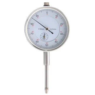
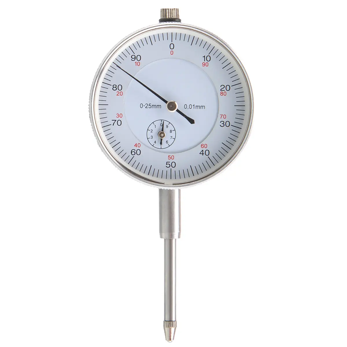
The Analog Dial Indicator 0.01mm serves as a high-accuracy instrument designed to measure precise linear distances, surface height variations, flatness, and component alignment. Technical users commonly employ this mechanical gauge during the tramming process to verify that a CNC machine’s spindle axis sits perfectly perpendicular to the machining bed surface. By utilizing mechanical displacement, the analog display converts minuscule physical variations of the contact plunger into readable rotational movements across a clearly marked dial face.
The device features standard rear mounting configurations, ensuring immediate compatibility with standard magnetic stands, articulated arms, and custom fixture systems. It operates completely independently of electrical power rails, allowing seamless deployment in diverse workshop environments without risk of electromagnetic interference or signal degradation.
Applications
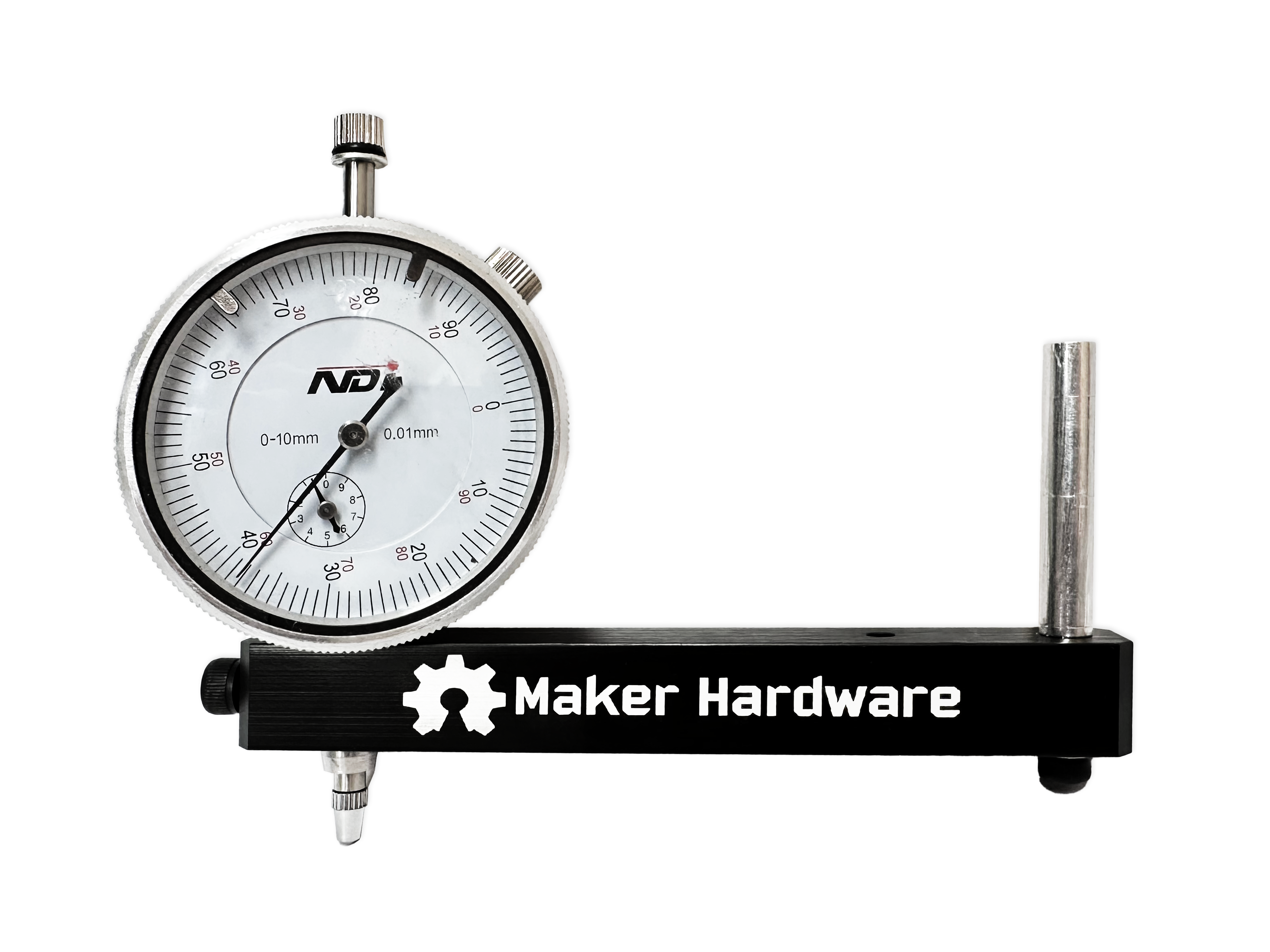
Machinists and mechanical engineers implement this analog instrument across metalworking, quality control inspection, and precision CNC system calibration routines. Specifically, you can use it to detect runout on rotating shafts, check the parallel alignment of guide rails, and map surface variations across machine beds. For machine calibration, technical users frequently couple the dial indicator with an external fixture, such as the Tramming Arm – Aluminium, to check spindle alignment across a wide sweeping path.
To execute calibration, securely mount the indicator to the arm fixture and chuck the assembly directly into the machine collet. Lower the Z-axis until the plunger makes slight contact with the surface, then rotate the outer bezel to establish the zero datum point. Manually sweep the spindle assembly across the bed to observe needle deflection; any physical fluctuation highlights angular misalignment. Technicians then adjust the mechanical axes of the machine until the dial indicates minimal variation, securing consistent perpendicular alignment.
Technical Specifications
Maker Store Tips and Tricks
-
Avoid applying lateral force to the indicator plunger during setup; only allow vertical movement along its travel axis to prevent internal binding.
-
Always clean the indicator tip and the target surface before measurement, as microscopic debris or dust particles will distort 0.01mm readings.
-
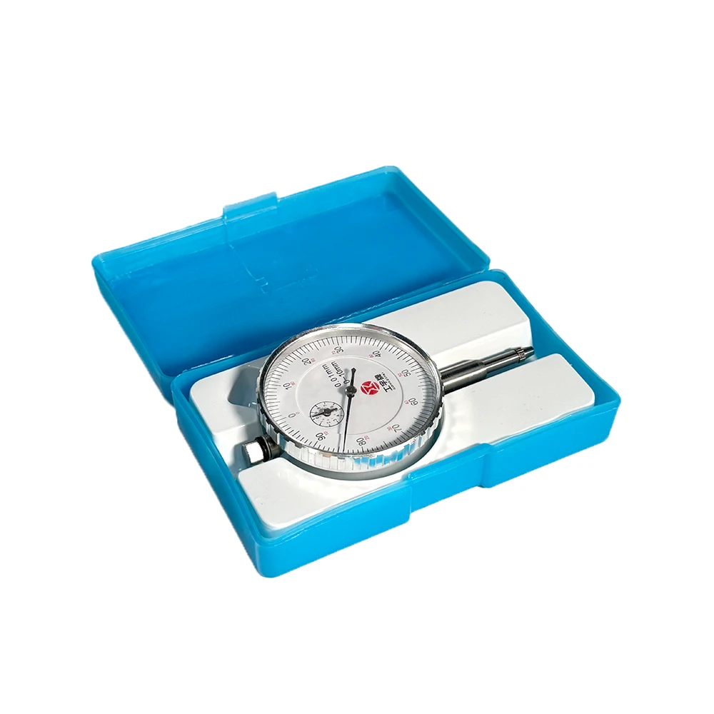
Store the device inside its protective storage case under low humidity conditions whenever it is not mounted to a stand or fixture.
How to Use the Dial Indicator with the Tramming Arm for CNC Alignment:
- Mount the Dial Indicator: Attach the Analog Dial Indicator to the Tramming Arm – Aluminium using its mounting hole. Ensure it is secured properly.
- Install on the Spindle: Insert the tramming arm into the CNC spindle collet and tighten it securely.
- Position Over the Work Surface: Lower the spindle until the dial indicator’s plunger lightly touches the CNC table or spoilboard.
- Zero the Indicator: Rotate the outer bezel to set the dial’s zero point at the current reading.
- Sweep the Table Surface: Slowly rotate the spindle by hand, allowing the indicator to sweep across the surface.
- Check for Variations: Observe the dial movement—if the needle fluctuates, the spindle is misaligned.
- Adjust as Needed: Loosen and adjust the machine’s spindle or table until the dial indicator shows minimal variation, ensuring a perfectly trammed spindle.