Description
Technical Overview
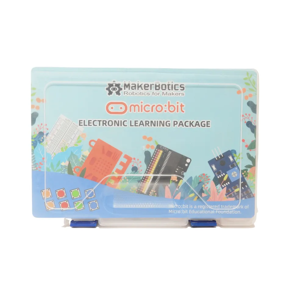
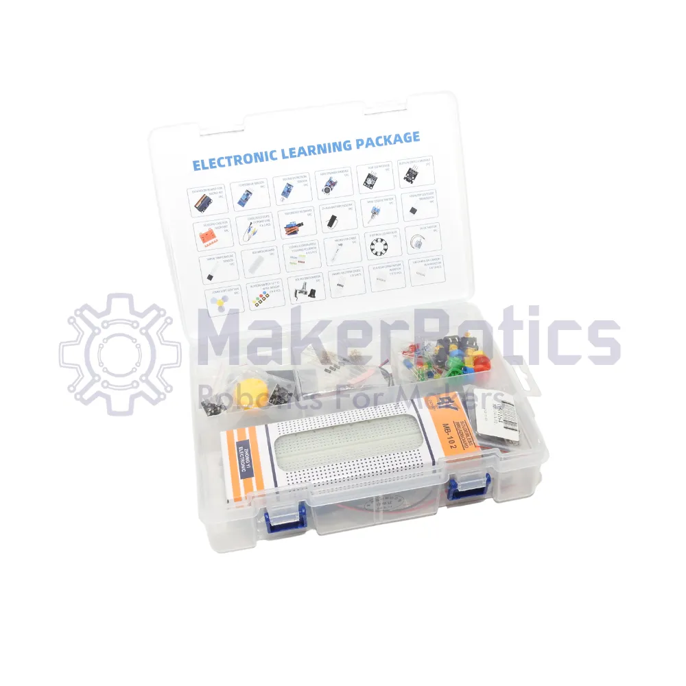
This electronic learning package serves as a comprehensive prototyping and developmental hardware ecosystem designed to interface directly with a micro:bit microcontroller using a dedicated breakout board and an 830-hole breadboard layout. The kit breaks out the microcontroller pins to facilitate solderless circuit configuration, enabling signal routing between the central processor and a diverse range of digital and analogue peripherals. Furthermore, the system establishes cross-compatibility, interfacing with both the V1 and V2 hardware architectures of the micro:bit platform.
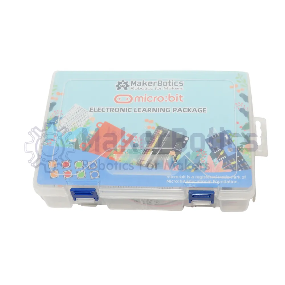
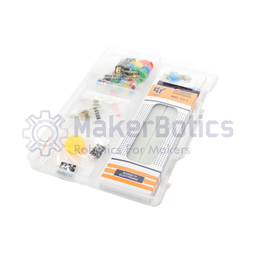
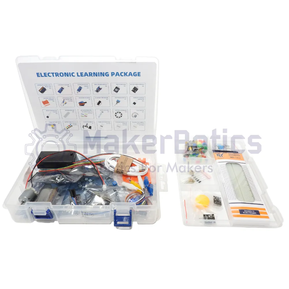
By supplying a modular array of sensors, discrete semiconductors, passives, and electromechanical actuators, the package establishes the physical infrastructure required to construct complex electronic networks. The inclusion of power management accessories, prototyping leads, and protective housing components allows technical users to build and evaluate custom firmware routines within a single, integrated development environment.
Applications
Institutions widely deploy this assembly within science, technology, engineering, and mathematics (STEM) educational frameworks to teach circuit design, physical computing, and firmware programming. Technicians and students regularly utilize the included modules to study robotics control loops, data acquisition workflows, and signal conditioning techniques.
Specifically, the components allow for the assembly of automated systems, sensor-driven telemetry nodes, and fundamental motion control setups. The diversity of the input and output breakout devices—ranging from optoelectronic infrared arrays to electromechanical motor configurations—permits rapid prototyping and multi-disciplinary validation within electronics laboratories, academic workshops, and prototyping environments.
Packing List
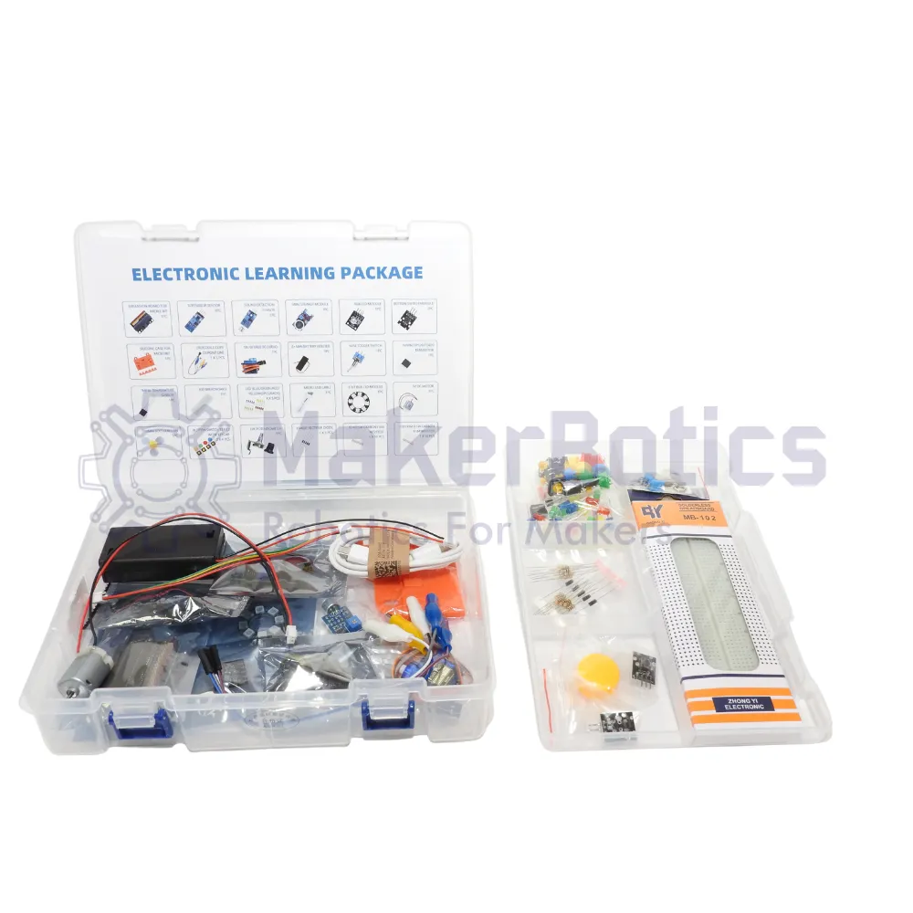
Included in the kit are the following:
- Micro:bit Battery Holder – 2xAA
- Micro:bit Breakout Board
- Micro USB Cable
- SG-90 Mini Servo(1.6kg) – 180 Degree
- 5V DC motor
- 70mm Leaf fan
- 10K potentiometer
- Active Buzzer
- 830 hole BreadBoard
- Sound detection Module
- Breadboard Power Supply Module
- TIP233 Touch Sensor
- PS2 Joystick
- UNL2003 Stepper motor driver module
- 4x Button Switches
- 5x Crocodile Clips
- TMP36 Temperature Sensor
- NPN TIP120 Transistor
- Mini Toggle Switch
- RGB LED Module
- Mini Speaker Module
- Sound Detection module
- TRT5000 IR sensor module
- 8 bit RGB LED Module
- Button Switch module x2
- 100 Ohm 0.5W resistors x10
- 10k Ohm 0.5W resistors x10
- Yellow LED x5
- Blue LED x5
- Green LED x5
- Red LED x5
- Silicone Case For Micro:Bit microcontroller
Please note: The micro:bit microcontroller is not included. It can be purchased here.
Maker Store Tips and Tricks
-
Ensure correct pin-to-row alignment when inserting the micro:bit breakout board into the 830-hole breadboard to avoid cross-connecting adjacent signal lines.
-
Deploy the external breadboard power supply module when running high-current induction modules, such as the 5V DC motor or the servo, to prevent voltage sags on the microcontroller rail.
-
Always verify resistor color-coding or check resistance values using a digital multimeter prior to populating the breadboard to protect sensitive LED and transistor paths.