Description
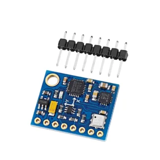
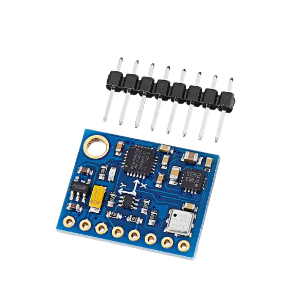
Combining three distinct sensors, the 10DOF IMU Module functions as an inertial measurement unit (IMU), facilitating the measurement of various types of motion and orientation. IMU sensors play a pivotal role in robotics, aiding in mapping endeavours where precise orientation is essential for accurate mapping and navigation. The integration of these three sensors enhances the capabilities of this module, broadening its utility across a diverse array of applications.
Specifications
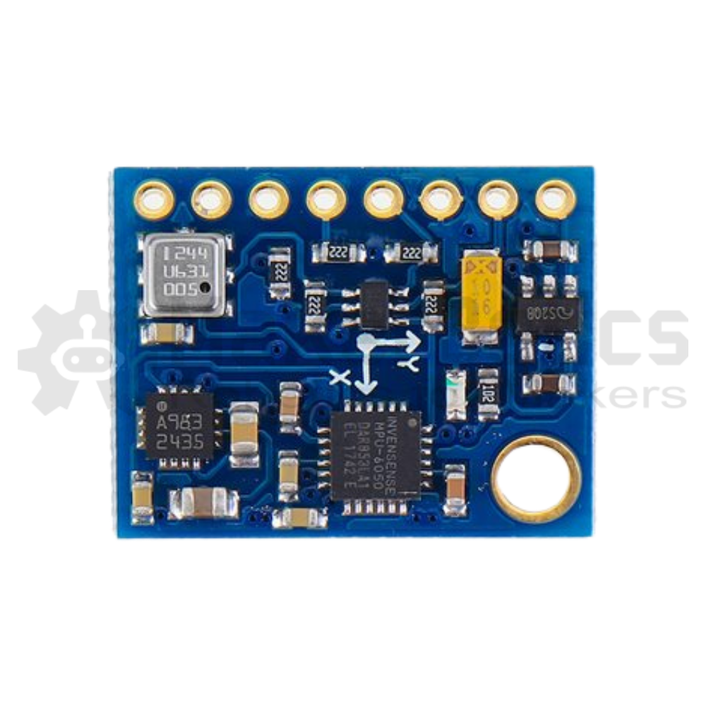
- 3 onboard sensors; MPU6050 + HMC5883L + BMP180, giving a total of 10DOF
- I2C communication
- 3.3-5V Input Voltage
- Built in low noise linear LDO voltage regulator
- Built-in onboard filters, which reduce noise from motors and other high-current electronics
- Built-in Power LED
- Small footprint of 20mm x 16mm.
Features
Incorporating three sensors into a compact and feature-rich package, the 10DOF IMU Module offers a comprehensive solution. The sensors featured in this IMU include:
- MPU6050: A widely utilized six-axis accelerometer and gyroscope sensor capable of measuring linear acceleration and rotational velocity in three dimensions. It finds extensive application in robotics and mapping endeavors.
- HMC5883L: A three-axis magnetometer proficient in measuring magnetic fields across three dimensions, commonly employed in compass applications.
- BMP180: A versatile pressure and temperature sensor adept at measuring barometric pressure and temperature, frequently utilized for altitude and weather monitoring.
By amalgamating these three sensors, the 10DOF IMU module facilitates the acquisition of diverse data concerning an object’s motion and orientation, encompassing acceleration, rotation, magnetic fields, pressure, and temperature. This wealth of data finds utility across various domains, including navigation, robotics, drone flight stabilization, and environmental mapping, among others.
Connectivity:
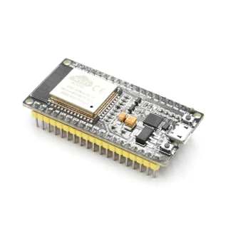
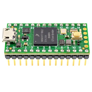
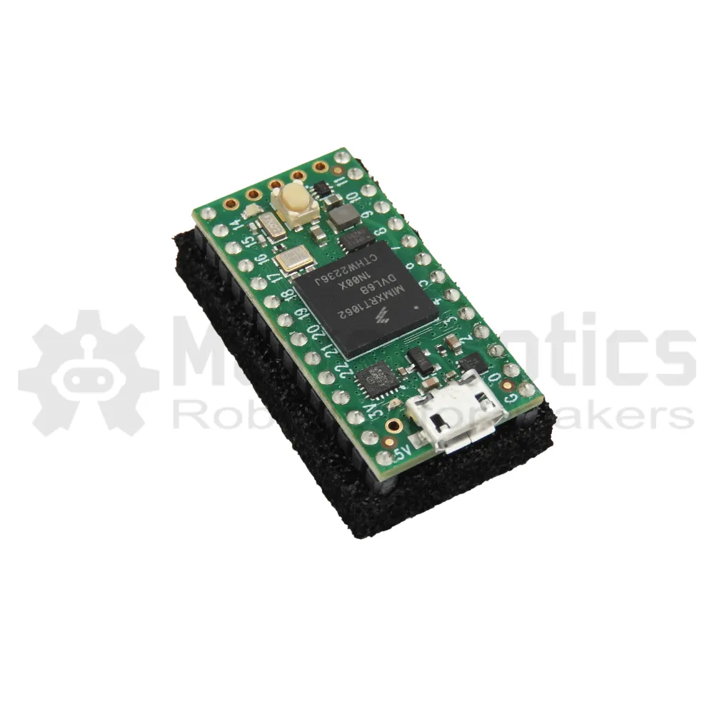
This sensor module communicates via the I2C protocol, allowing for more I2C-enabled devices to be added to your projects. It can be interfaced with either 3.3V or 5V compatible microcontrollers such as the ESP32, Teensy or Arduino microcontrollers. No logic level shifter is required.
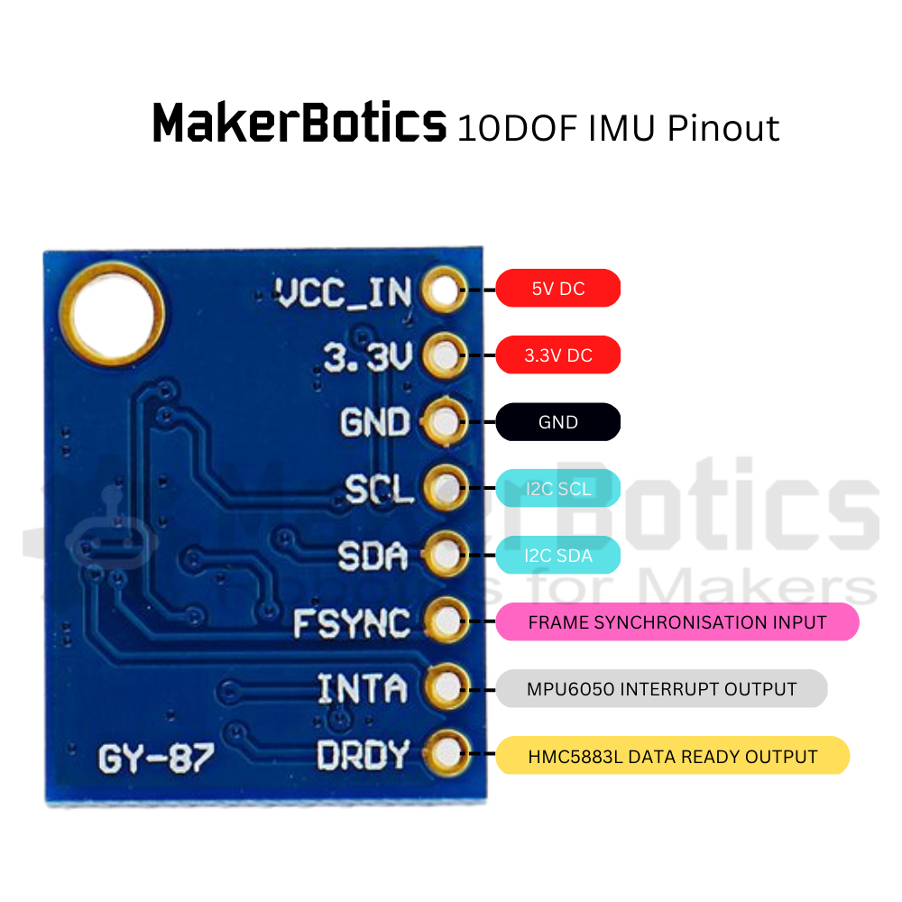
Pinout Diagram:
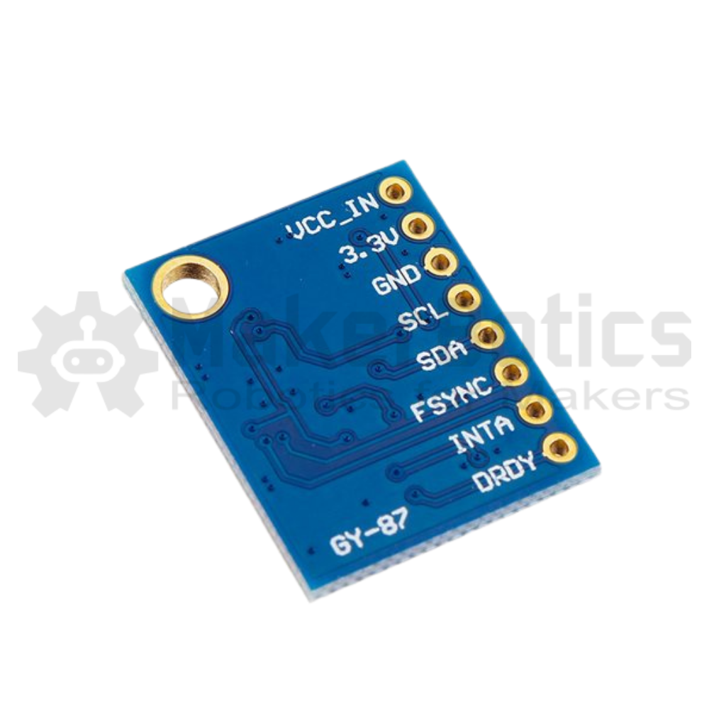
Displayed below is a pinout diagram delineating the power inputs and digital communication pins. In most applications, communication primarily revolves around the I2C pins. However, the FSYNC, INTA, and DRDY pins find relevance in specialized applications.
Uses:
- Drone flight stabilization
- Mapping & Navigation
- Robotics
Documentation: