Description
Technical Overview
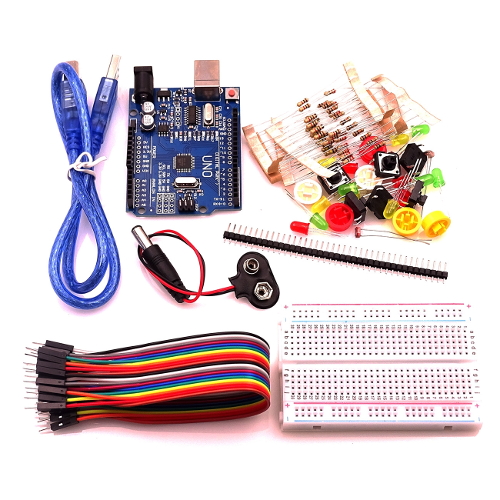
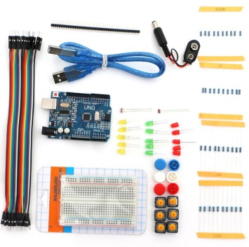
The Arduino Starter Pack #2 provides a foundational hardware bundle. Specifically, it assists technical users in introductory electronics prototyping and embedded systems development. In addition, this entry-level platform allows you to construct, code, and test basic electronic circuits. Consequently, you can complete these tasks without specialized diagnostic or thermal soldering equipment. Furthermore, an Arduino UNO R3 compatible microcontroller board sits at the core of the system. This board serves as the central processing unit to execute your control firmware.
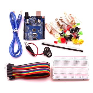
To facilitate component interconnection, the bundle includes a 400-hole solderless breadboard. It also provides a set of 20 male-to-male Dupont jumper cables. Therefore, you can establish secure electrical paths quickly. As a result, you can modify your circuit designs dynamically. Additionally, the kit integrates discrete optoelectronic and control elements. In particular, it features five assorted coloured light-emitting diodes (LEDs) and six tactile push buttons with mixed colour caps. It also contains two photoresistors for environment-based optical sensing. Next, a collection of fixed-value resistors regulates current flow across the circuit pathways. These parts include 220 Ω, 1K, 10K, and 100K variants. Finally, a 9V battery snap connector supplies the primary external DC input voltage to power the complete assembly.
Applications
Students, educators, and electronics hobbyists commonly use this component bundle. Specifically, they implement it as a practical training tool to master C++ firmware design and circuit analysis. For this reason, the kit functions as the physical hardware baseline for introductory laboratory experiments. Consequently, you can interface digital inputs, analog sensors, and visual outputs directly to a programmable microcontroller. For instance, individuals frequently utilize the assorted LEDs to practice fundamental output control. They also use them to test pulse-width modulation (PWM) routines.
Furthermore, technical users can pair the tactile push buttons with the microcontroller. Thus, they easily design digital input reading routines. For example, you can develop debouncing algorithms or button-controlled switching logic. Afterwards, you can combine the integrated photoresistors with the fixed resistors. This layout creates a standard voltage divider network. As a result, developers can build light-sensitive instrumentation. Typical examples include ambient light level logging systems and optical threshold alarms. Ultimately, these configurations serve as foundational exercises before you expand into complex automation equipment, sensor monitoring nodes, and small-scale electronic sub-assemblies.
Includes:
- 1 × Arduino UNO R3
- 20 × Male to Male Dupont cable
- 1 × USB cable
- 1 × 400 holes Breadboard
- 5 × 3 colours of LED lights(random)
- 10 × Resistor 220ohm
- 10 × Resistor 1K
- 10 × Resistor 10K
- 10 × Resistor 100K
- 2 × Photoresistor 5516
- 6 × Button(with the mixed colour caps)
- 1 × 9V Battery Connector
- 4 × 2.54mm Pin
Maker Store Tips and Tricks
-
Always place a 220 Ω or 1K resistor in series with the LEDs to limit current flow and protect the optoelectronic devices from electrical strain.
-
Disconnect the 9V battery snap or the USB power source before altering any wiring paths on the solderless breadboard to prevent short circuits.
-
Utilise the official, free Arduino Integrated Development Environment (IDE) to compile your C++ code and upload firmware to the microcontroller board.