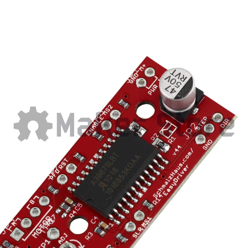
Description
Please Note:Do not connect or disconnect a motor while the driver is energized. This will cause permanent damage to the A3967 IC. |
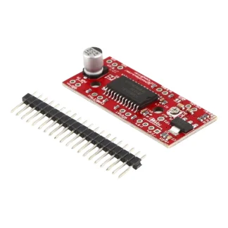
The EasyDriver is a simple to use stepper motor driver, compatible with anything that can output a digital 0 to 5V pulse (or 0 to 3.3V pulse if you solder SJ2 closed on the EasyDriver). The EasyDriver requires a 6V to 30V supply to power the motor and can power any voltage of stepper motor. The EasyDriver has an on board voltage regulator for the digital interface that can be set to 5V or 3.3V. Connect a 4-wire stepper motor and a micro-controller and you’ve got precision motor control!
EasyDriver drives bi-polar motors, and motors wired as bi-polar. I.e. 4, 6, or 8 wire stepper motors. This EasyDriver V4.4 provides much more flexibility and control over your stepper motor, when compared to older versions. The micro-step select (MS1 and MS2) pins of the A3967 are broken out allowing adjustments to the micro-stepping resolution. The sleep and enable pins are also broken out for further control.
Specifications:
- A3967 Micro-stepping Driver
- MS1 and MS2 pins broken out to change micro-stepping resolution to full, half, quarter and eighth steps (defaults to eighth)
- Compatible with 4, 6, and 8 wire stepper motors of any voltage
- Adjustable current control from 150mA/phase to 750mA/phase
- Power supply range from 6V to 30V. The higher the voltage, the higher the torque at high speeds.
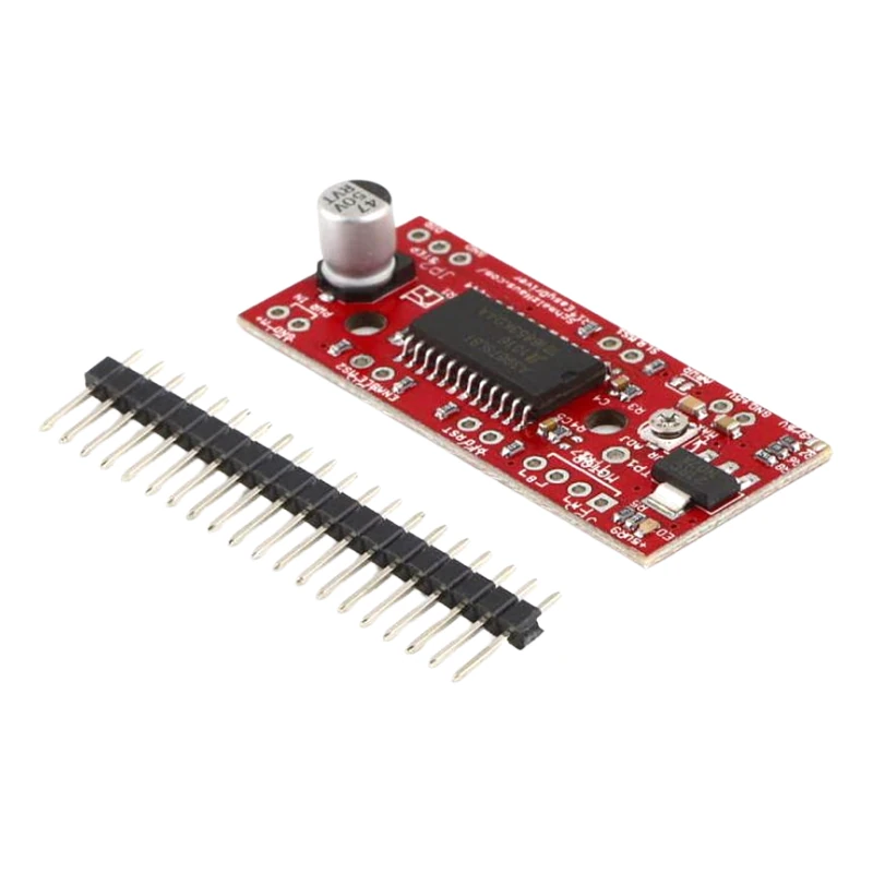
- Teensy Header included
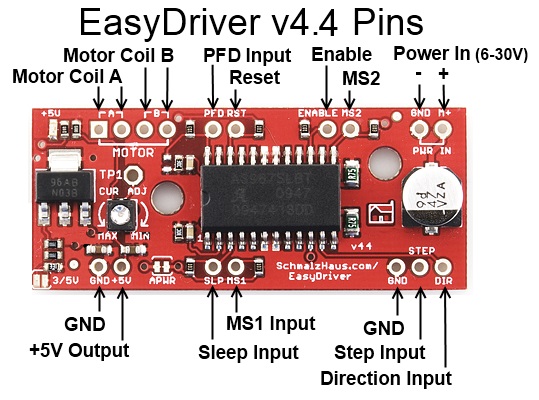
Quick Pin Description:
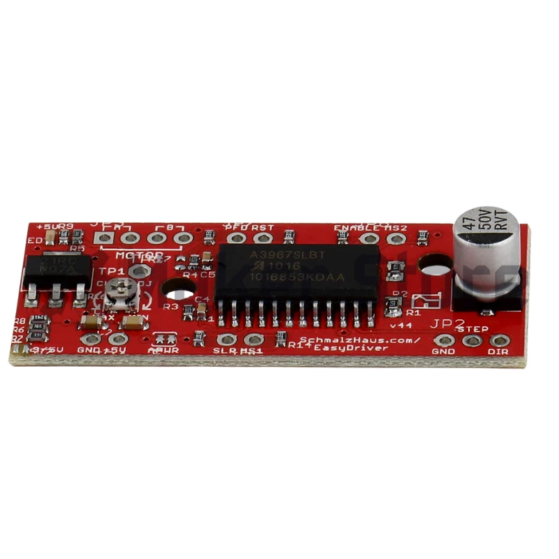
Please see the Allego A3967 data sheet linked above for complete technical details. The Easy Driver is basically just a breakout board for this driver chip, so the datasheet is your best source of information about how it all works. However, if all you need is a reference to the pins, here you go:
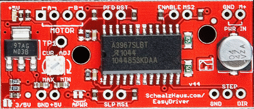
- GND : There are three GND (Ground) pins on the Easy Driver. They are all connected together inside the board. Connect the negative side of your power supply, as well as from any other boards you are using to drive the Easy Driver to one or more of the GND pins.
- M+ : This is the power input to the Easy Driver. Connect this to the positive power supply lead. This should be a 6V to 30V, 2A (or more) power supply that is clean (low ripple).
- A and B : (four pins) These are the motor connections. See below diagrams for how to hook these up. A and B are the two coils of the motor, and can swap the two wires for a given coil (it will just reverse the direction of the motor). Make CERTAIN that this connection to the motor is solid, and NOT through a connector that has any chance of intermittent contact (which will fry the motor driver chip).
- STEP : This needs to be a 0V to 5V (or 0V to 3.3V if you’ve set your Easy Driver that way) digital signal. Each rising edge of this signal will cause one step (or micro-step) to be taken.
- DIR (Direction) : This needs to be a 0V to 5V (or 0V to 3.3V if you’ve set your Easy Driver up that way) digital signal. The level if this signal (high/low) is sampled on each rising edge of STEP to determine which direction to take the step (or micro-step).
That’s it – those are the only signals that you absolutely need to connect to anything. All the rest below are optional – in other words, the Easy Driver sets them to reasonable default values.
- MS1/MS2 : These digital inputs control the micro-stepping mode. Possible settings are (MS1/MS2) : full step (0,0), half step (1,0), 1/4 step (0,1), and 1/8 step (1,1 : default).
- RST (reset) : This normally high input signal will reset the internal translator and disable all output drivers when pulled low.
- SLP (sleep) : This normally high input signal will minimize power consumption by disabling internal circuitry and the output drivers when pulled low.
- ENABLE : This normally low input signal will disable all outputs when pulled high.
- PFD : This one is complicated – please see the datasheet for more information. We default it to slow decay mode, but you can over-ride with your own voltage on this pin. (or by populating R17)
- 5V : This is an OUTPUT pin that will provide either 5V (default) or 3.3V from the voltage regulator, at a small amount of current (say 50mA – depends on input voltage) to power a circuit that you may need powered. If you cut jumper APWR (SJ1) then you can use the 5V pin as a VCC input to the Easy Driver, powering it with your own VCC supply.
(Source: EasyDriver Website)
Resources:
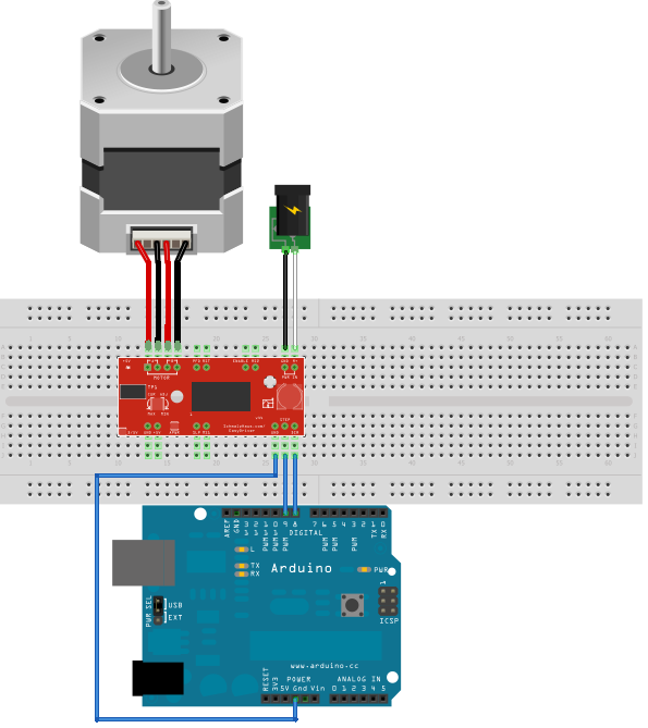
Wiring Example: