What if you could turn a simple temperature sensor into a physical temperature gauge?
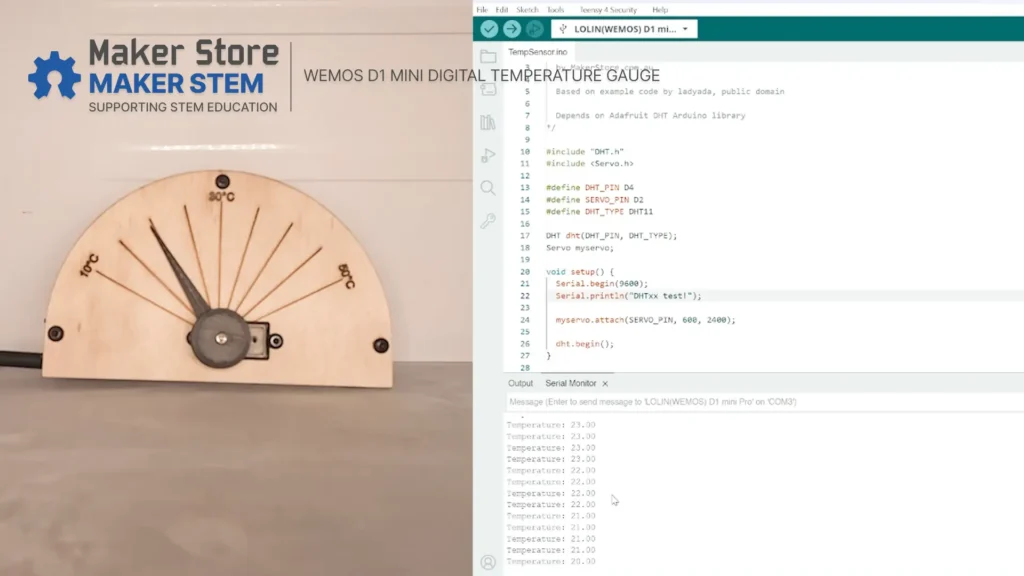
In this Maker STEM project, we’ll build a temperature gauge using a Wemos D1 Mini Pro, a DHT11 temperature and humidity sensor, and an MG90S servo motor.
The DHT11 measures the temperature, while the Wemos D1 Mini Pro processes the sensor readings and controls the servo motor. The servo then moves a physical dial hand to display the current temperature on the laser-cut dial.
This project combines electronics, programming, 3D printing, laser cutting, and mechanical assembly into one hands-on STEM project.
Safety note: Soldering should be carried out under appropriate supervision. Always use suitable safety equipment and follow safe soldering practices.
What You’ll Need
Electronics
| Part | Quantity |
|---|---|
| MG90S Servo Motor | 1 |
| Wemos D1 Mini Pro | 1 |
| Wemos DHT11 Shield | 1 |
Mechanical Hardware
| Part | Quantity |
|---|---|
| 30 mm Spacer | 2 |
| M3 × 40 mm Button Head Screw | 2 |
| M3 × 6 mm Button Head Screw | 2 |
| M3 × 8 mm Button Head Screw | 2 |
| M3 Nuts | 4 |
Custom Parts (File Downloads)
Download the complete CAD files for this project, including all laser-cut and 3D-printed parts.
Download the Complete Temperature Gauge CAD Files
| Part | Quantity |
|---|---|
| Dial Face – laser-cut plywood | 1 |
| Rear Face – laser-cut plywood | 1 |
| ESP Bracket – 3D printed | 1 |
| Dial Hand – 3D printed | 1 |
Tools and Accessories
- Soldering iron
- Solder
- Helping hands or PCB holder
- Soldering fume absorber
- Flush cutters
- Micro-USB cable
- Male-to-male jumper cable
- Computer with Arduino IDE
Mechanical Assembly
Step 1: Mount the Servo Motor

Start by mounting the MG90S servo motor onto the back of the dial face.
Use the M3 × 8 mm button head screws and M3 nuts to secure the servo in place.
Make sure the servo shaft is aligned with the centre opening of the dial.
Step 2: Attach the Dial Hand


Next, attach the 3D-printed dial hand to the servo shaft.
Use the screw supplied with the servo motor to hold the dial hand in place.
Don’t fully tighten the screw yet. The dial hand will need to be adjusted later during calibration.
Step 3: Assemble the Dial
Place the rear face behind the dial face.
Use the two 30 mm spacers between the plates.
Secure the plates through the top and right-hand mounting holes using the M3 × 40 mm button head screws and M3 nuts.
Make sure the two plates are aligned before fully tightening the hardware.
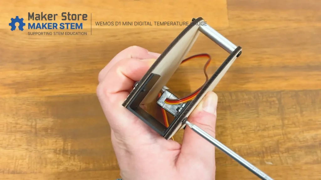
Step 4: Install the ESP Bracket
Insert the 3D-printed ESP bracket between the two plates on the left-hand side.
Align the mounting holes in the bracket with the corresponding holes in the dial and rear face.
Secure the bracket using the M3 × 6 mm screws.
These screws are designed to self-thread into the 3D-printed plastic, so tighten them carefully.
Electronic Assembly
Step 5: Prepare the Wemos D1 Mini Pro

Before connecting the electronics, solder the female headers onto the Wemos D1 Mini Pro.
Make sure the headers are straight and securely soldered to the board.
Safety note: Soldering should be carried out under appropriate supervision. Use suitable safety equipment and avoid touching the hot soldering iron or freshly soldered components.
Step 6: Prepare the DHT11 Shield
Next, solder the female stacking headers onto the DHT11 shield.
Once the headers are installed, plug the DHT11 shield onto the Wemos D1 Mini Pro.
Make sure the pins are correctly aligned before pressing the boards together.
Step 7: Connect the Servo
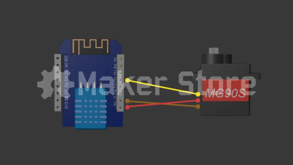
Connect the MG90S servo to the DHT11 shield using the male-to-male adapter cable.
The servo wires should be connected as follows:
| Servo Wire | Connection |
|---|---|
| Red | 5V |
| Brown | GND |
| Orange | D2 |
The red wire provides power, the brown wire connects to ground, and the orange wire carries the control signal to D2.
Important: The DHT11 sensor uses D4 for its data signal, while the servo uses D2. Do not connect the servo signal wire to D4.
Step 8: Install the Electronics
Place the assembled Wemos D1 Mini Pro and DHT11 shield into the 3D-printed ESP bracket.
Feed the servo wires neatly between the dial and rear face.
Make sure the wires don’t interfere with the servo mechanism or the movement of the dial hand.
If necessary, use a small cable tie to keep the wires organised.
Upload the Code
Step 9: Connect the D1 Mini Pro
Connect the Wemos D1 Mini Pro to your computer using a micro-USB cable.
Open Arduino IDE.
Step 10: Select the Board
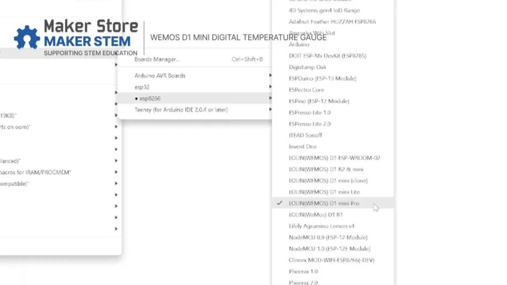
In Arduino IDE, select the Wemos D1 Mini Pro board.
Go to:
Tools → Board → ESP8266 Boards → LOLIN(WEMOS) D1 & mini Pro
Then select the COM port connected to your Wemos D1 Mini Pro.
Step 11: Open the Arduino Sketch
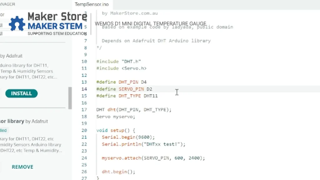
Open the temperature gauge Arduino sketch in Arduino IDE.
The project uses the following pins:
- DHT11 → D4
- Servo → D2
Make sure the code matches these connections before uploading.
Step 12: Install the DHT Library
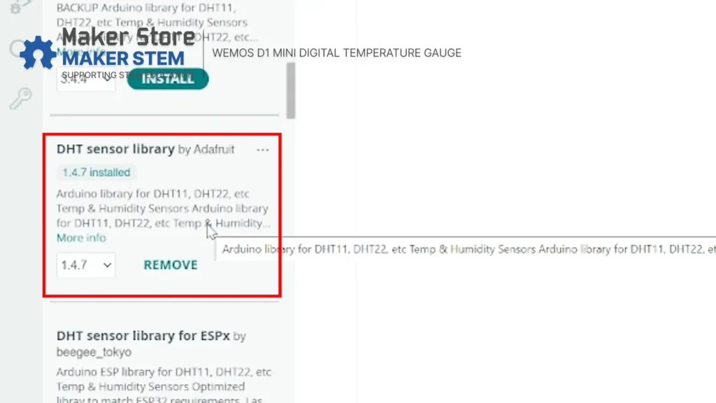
This project uses the DHT sensor library by Adafruit.
In Arduino IDE, open:
Tools → Manage Libraries
Search for:
DHT sensor library
Install the library by Adafruit.
If Arduino IDE asks you to install any additional required libraries, install those as well.
Step 13:Copy and Upload the Code
Copy the code below and paste it into a new Arduino sketch.
#include "DHT.h"
#include

#define DHT_PIN D4
#define SERVO_PIN D2
#define DHT_TYPE DHT11

DHT dht(DHT_PIN, DHT_TYPE);
Servo myservo;

void setup() {
  Serial.begin(9600);
  Serial.println("DHTxx test!");

  myservo.attach(SERVO_PIN, 600, 2400);

  dht.begin();
}

void loop() {
  delay(2000);

  float t = dht.readTemperature();

  if (isnan(t)) {
    Serial.println("Failed to read from DHT sensor!");
    return;
  }

  Serial.print("Temperature: ");
  Serial.println(t);

  int pulse = map(t, 10, 50, 2400, 600);

  myservo.writeMicroseconds(pulse);
}
After copying the code, upload it to the Wemos D1 Mini Pro.
Wait for the upload to complete before disconnecting the USB cable.
Test the Temperature Reading
Step 14: Open the Serial Monitor
Open the Serial Monitor in Arduino IDE.
Set the baud rate to 9600.
You should now see temperature readings from the DHT11 sensor.
For example:
Temperature: 22.00
Temperature: 22.00
Temperature: 23.00
The servo should also respond to the temperature reading by moving the dial hand.
This allows you to confirm that the sensor and servo are working correctly before calibrating the physical dial.
Calibrate the Dial
Step 15: Adjust the Dial Hand
Now it’s time to calibrate the temperature gauge.
Check the temperature displayed in the Serial Monitor.
For example, if the sensor reads 22°C, the dial hand should point to 22°C on the physical dial.
To calibrate the dial:
- Loosen the screw holding the dial hand onto the servo shaft.
- Carefully adjust the angle of the dial hand.
- Align the hand with the temperature shown in the Serial Monitor.
- Tighten the screw to secure the dial hand.
Be careful not to force the servo beyond its normal range of movement.
You’re Done!

Your temperature gauge is now ready to use.

The DHT11 sensor measures the temperature, the Wemos D1 Mini Pro processes the reading, and the MG90S servo moves the physical dial hand to display the temperature.
This project combines sensors, microcontrollers, programming, servo motors, 3D printing, and laser cutting into one hands-on STEM project.
Want to take it further?
- Display humidity as well as temperature
- Add an LED indicator for different temperature ranges
- Add an OLED display
- Log temperature readings over time
- Send temperature data over Wi-Fi
- Create an automatic fan or cooling system
Keep experimenting, keep building, and see what you can make!